HES 9600 Installation Guide
The HES 9600 surface-mounts to wood, hollow metal, and aluminum storefront frames without frame cutting using the 9000-MTK template kit. Hanchett Entry Systems (HES), an ASSA ABLOY company, designed the 9600 for fast installation—a complete retrofit takes under 30 minutes on pre-wired frames. This guide covers the installation process for all frame types, voltage configuration, and fail-secure/fail-safe mode selection.
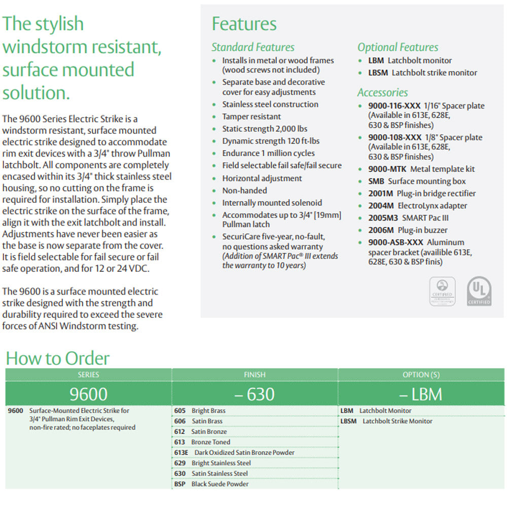
Surface-Mount Design
The HES 9600's 3/4" thick stainless steel housing mounts directly to the frame face—no cutting or routing required. Installation typically takes 30 minutes or less.
What tools are required to install the HES 9600?
Install the HES 9600 using a drill, 1/4"-20 tap, Phillips screwdriver, and wire strippers. For hollow metal frames, you'll also need blind nuts (provided) instead of tapping. The optional 9000-MTK template kit simplifies hole positioning.
Required Tools
- Drill with 13/64" bit — For pilot holes
- 1/4"-20 tap — For solid frames (or blind nuts for hollow)
- Phillips screwdriver — For cover plate
- Wire strippers — For electrical connections
- Multimeter — For voltage verification
- 9000-MTK template (optional) — For precise hole marking
How do I install the HES 9600 on a metal frame?
Mount the HES 9600 on metal frames using Securitron BN-250 blind nuts for hollow sections or 1/4"-20 tapped holes for solid frames (14 gauge or heavier). The strike requires 4 mounting points arranged in a vertical pattern. For detailed frame-specific procedures, see the hollow metal frame installation guide or aluminum storefront installation guide. Follow these 9 steps:
Step 1: Position the Template
Use the 9000-MTK template or the paper template included in the package to mark mounting hole locations. Position the template so the strike opening aligns with the exit device latchbolt centerline. The strike should be vertically centered on the latchbolt.
Step 2: Drill Mounting Holes
Drill four 13/64" pilot holes at the marked locations. For hollow metal frames, drill through both the face and back of the frame to insert blind nuts. For solid frames, drill to a depth sufficient for 1/4"-20 threads (minimum 3/8").
Step 3: Prepare Mounting Points
For hollow frames: Insert blind nuts from the back side and pull to expand. For solid frames: Tap 1/4"-20 threads into each pilot hole. Clean debris from holes before proceeding.
Step 4: Route Wiring
Run power wiring through the frame to the strike location. Use a minimum 18 AWG wire for runs up to 100 feet. Leave sufficient slack for connections—approximately 8 inches of wire at the strike location.
Step 5: Configure Voltage
Connect the appropriate pigtail for your voltage: Red(+) and Black(-) for 12V, or Violet(+) and Red/Green(-) for 24V. Insulate unused pigtails with electrical tape. See wiring diagrams for details.
Step 6: Mount the Strike Base
Remove the decorative cover from the strike body. Position the base on the frame, aligning the mounting holes. Install four 1/4"-20 screws and tighten evenly in a cross pattern. Do not overtighten.
Step 7: Test Operation
Apply power and test the strike release. The solenoid should retract smoothly when energized. Test with the door closed to verify latchbolt engagement and release under load.
Step 8: Adjust as Needed
The strike has a vertical adjustment slot allowing ±1/8" vertical movement. Loosen the mounting screws, adjust position, and retighten. The horizontal depth is fixed.
Step 9: Install Cover
Snap the decorative cover onto the strike base. Ensure the cover is fully seated and aligned with the frame face.
Test strike operation before installing the cover. It's easier to make adjustments with the mechanism exposed. Verify the latchbolt enters the strike opening smoothly and releases without binding.
How do I install the HES 9600 on a wood frame?
Mount the HES 9600 on wood frames using the provided wood screws in pre-drilled pilot holes. Wood installation is simpler than metal because no tapping or blind nuts are required.
Wood Frame Procedure
- Position template and mark four mounting hole locations
- Drill 3/16" pilot holes at marked locations
- Route power wiring through frame or surface raceway
- Connect appropriate voltage pigtail (12V or 24V)
- Mount strike base using #12 wood screws
- Test operation and adjust vertical position
- Install decorative cover
How do I configure fail-secure vs fail-safe mode?
The HES 9600 ships in fail-secure mode and can be converted to fail-safe using the internal selector. Fail-secure means the strike locks when power is removed (requires power to unlock). Fail-safe means the strike unlocks when power is removed (requires power to lock).
| Mode | Default State | When to Use |
|---|---|---|
| Fail-Secure | Locked (power to unlock) | Security priority, windstorm compliance |
| Fail-Safe | Unlocked (power to lock) | Fire egress priority |
Converting to fail-safe mode removes the HES 9600's windstorm rating. For Florida Building Code (FL# 14307) compliance, the strike must remain in fail-secure mode.
Learn more about fail-safe vs fail-secure configuration →
What are common installation mistakes to avoid?
The most common installation errors are incorrect voltage connection, misaligned strike positioning, and using fail-safe mode in windstorm applications. Avoid these issues by following the checklist below:
Installation Checklist
- Verify exit device has 3/4" or smaller Pullman latchbolt
- Confirm 12V or 24V DC power availability (not AC)
- Connect correct pigtail pair for your voltage
- Insulate unused pigtails to prevent shorts
- Center strike opening on latchbolt—not offset
- Use fail-secure mode for windstorm compliance
- Test operation before installing cover
- Verify door closes and latches properly after installation
View troubleshooting guide for installation problems →
Download the complete HES 9600 installation instructions from the manufacturer: